Calcium
Looping
CCS Spring 2013
3.1 BACKGROUND
Repeated Cycles of Calcination and Carbonation:
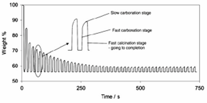
Figure 3.1 : Decrease in carrying capacity with the number of cycles (Blamey et. al, 2010)
Calcium carbonate has a molecular weight of 100 g/mol and calcium oxide has a molecular weight of 56 g/mol. As illustrated in Figure 3.1 , there is a rapid and complete decomposition of calcium carbonate to the oxide (calcination). However, carbonation is characterized by a fast initial rate followed by a transition to a slow rate controlled by diffusion of the reacting species through the CaCO3 product layer.
The majority of the observed fast part of the carbonation reaction occurs inside pores narrower than ∼150 nm. The initial fast part of the reaction is due to the filling of small pores (<150 nm) in the grains comprising the particles. In carbonation, porous calcium oxide (molar volume of 16.9 cm3/g) is formed in place of calcium carbonate (36.9 cm3/g), hence the calcium carbonate that forms on the surface of a calcium oxide particle during carbonation has a larger molar volume. As a result, when the CaCO3 product layer (which is less porous to the flow of CO2) is formed, it can grow over the mouth of pores and seal them off, impeding CO2 transport. Once a critical product layer is formed (~50 nm), a much slower process involving diffusion through the CaCO3 on the walls of large pores controls the reaction rate.
3.2 ADVANTAGES
Ca- looping technology offers several technical advantages over amine-scrubbing. Both carbonator and calciner can use fluidized bed technology, owing to the good gas-solid contacting and uniform bed temperature. This fluidized bed technology has already been demonstrated at large scale: large (460MWe) atmospheric and pressurized systems exist, and there isn’t a need for intensive scaling up as there is for the solvent scrubbing towers used in amine scrubbing (Blamey et al., 2010).
3.3 LIMITATIONS
Decrease in sorbent reactivity
Carrying capacity refers to the conversion of the carbonation reaction relative to its theoretical maximum of 1 mol CO2 reacted per mol of CaO (Fennell, 2007). It is evident from Figure 3.1 that the mass change upon carbonation decreases with the number of cycles, showing that the carrying capacity of the sorbent decreases upon its cycling through multiple CO2 capture and release cycles. Consequently, in order to allow efficient capture of CO2 in the Ca-looping cycle, more fresh sorbent is required due to sorbent deactivation. This increases the operating costs of the process as well as aggravates erosion and abrasion in the reactors.
Abanades et. al proposed a model to estimate the decay in CO2 capture capacity with cycling:
where XN is the carbonation conversion achieved after N cycles, fm=0.77 and fw=0.17 for a wide range of limestone and reaction conditions.
Some of the drop-off in carrying capacity can be attributed to the closure of small pores that do not reopen. There is a measured drop in total porosity in the calciner, indicating that one mechanism for the loss in measurable porosity is the sealing over of the mouths of the pores, isolating them inside the crystallite, so that no further reaction of CO2 with this sealed off internal area is possible (Fennell, 2007).
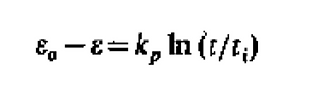
Next, sintering is responsible for much of the decrease in carrying capacity with an increasing number of cycles. It was found that after the first calcination, there is a peak pore volume at pore size of 35-45 nm. However, after carbonation for 5 min, almost all micropores are closed and there is a reduction in volume of pores narrower than 150 nm, indicating a change in microstructure due to sintering (Borgwardt, 1988). Sintering is the mechanism by which particles coalesce when heated at temperatures below their melting point (2500 degrees Celsius for CaO), and sintering is enhanced at the high carbonator and calciner temperatures. As micrograins coalesce, the specific surface area and porosity of the particle are reduced, with larger but fewer grains being formed. This is because as sintering begins, necks develop and grow at each point of contact between grains. In addition to the reduction of surface area, neck growth results in the contraction of distance between grain centers due to the displacement of matter by lattice diffusion. The grain array shrinks and total volume of micropores between grains is reduced. If the grain array remains continuous throughout the particle, the particle volume shrinks and the porosity declines simultaneously with surface area (Borgwardt, 1988). The rate of change of porosity has been modeled and an equation has been proposed by Coble:
where e is the porosity at time t, kp contains the physical constants of diffusion and eo and to are the porosity and time at which particle shrinkage occurs.
It is found that there is a sharp increase in sintering of particles within a relatively short timescale at temperatures above 1173K (Borgwardt, 1989). Similarly, if a sample is cycled above 1173K, a marked increase in deactivation of sorbent is observed. This is illustrated in Figure 3.2:
Figure 3.2 Variation of carrying capacity at different temperatures with the number of cycles (Blamey et. al, 2010)
As seen in Figure 3.2, more highly sintering environments (above 1173K) result in steeper gradients and a faster decline in carrying capacity when compared to less sintering environments (eg: 1113K), showing that sintering results in greater deactivation of the sorbent.
3.3.1 SOLUTIONS
Sorbent deactivation is a considerable problem for Ca-looping and a few potentially viable options to counteract sorbent deactivation are discussed below:
Hydration: Research has shown that hydration of calcined sorbents for CO2 capture is a promising reactivation strategy (Fennell, 2007). Hydration enables the breakup of the particles, causing improved porosity. During hydration, water molecules react with the CaO core to form Ca(OH)2. The Ca(OH)2, having a larger molar volume than CaO causes cracks to form and stress is generated in the outer layers of the particle, increasing friability. Addition of steam and water to calcined and highly sintered samples was found to improve CO2 capture ability, due to regeneration of <220 nm pores (Sun et. al, 2008). However, the generation of large quantities of fine particles could be problematic because they can become easily entrained in the fluidizing gas and be carried out of the reactor, negating the effects of reactivation.
Thermal pretreatment: For many sorbents, thermal pretreatment increased the carrying capacity for a few cycles, and thermally pretreated sorbents were found to be more reactive at a larger number of cycles. It has been found that thermally pretreated particles can retain enhanced activity (residual carrying capacity of ~15% compared to 7.5% of untreated particles) over up to 1000 cycles (Chen et al., 2009). With high-temperature calcination or carbonation, sintering occurs, leading to a decrease in sorbent pore volume for carbonation. Thermally pretreating limestone and dolomite by subjecting particles to an inert atmosphere for extended periods of 6 or 24 h resulted in sustained benefits in terms of the ability of the sorbent to retain carbon in repeated cycles of carbonation and calcination (Chen et al., 2009).
Doping: It was reported that modification of dolomite using acetic acid yielded a sorbent with significantly higher activity than that of the original sorbent. The carrying capacity of the modified dolomite was 60% after 20 cycles, as opposed to 26% with unmodified sorbent, using well-established fluidized bed technology (Li et al., 2008). Calcium magnesium acetate [CaMg(CH3CO2)4] is generated when dolomite is modified. It is known that although MgO is inert and does not absorb CO2, it enhances the dispersion in the CaO, thereby reducing its sintering and increasing its accessibility. The surface area and pore volume for calcined modified dolomite are much higher than those for calcined original sorbent after the same number of cycles. The pore volume and pore area distributions for the calcined modified dolomite are superior to those for the calcined original sorbent over the entire pore size range measured as well (Li et al., 2008). It was found that it is possible to significantly enhance the rate of carbonation for precipitated CaCO3 by doping with Li2CO3 as well (Blamey et al., 2010).
3.4 ENERGY EFFICIENCY
No power plant can be perfectly efficient, but it is still important to try to optimize the energy efficiency of the overall performance of the power plant. Because there are many components and processes involved in calcium looping, this means there will be various inherent inefficiencies, but this also presents many opportunities for creative improvements to energy efficiencies. The basic idea is that any heating, purification, or compression requires energy and decreases overall plant efficiency, while anything that is hot and is leaving the system can be used in heat exchange or used to power a steam cycle, thus increasing the overall plant efficiency.
Figure 2: Typical example scheme for Ca-looping post-combustion CO2 capture (Dean et al., 2011)
The calciner has a large energy input requirement and is a major source of inefficiency. The endothermic calcination of CaCO3 requires very high temperatures (about 900 to 950 degrees Celsius) to proceed at industrial rates. Therefore, any material present within the calciner is heated to the very high calciner temperature. This means that flows from the carbonator (at about 650 to 700 degrees Celsius) must be raised by about 250 degrees Celsius, while inflows from ambient temperatures (e.g. limestone, used to regenerate the sorbent) must be raised by about 900 degrees Celsius. The high temperature calciner can be heated in any number of ways, but the most explored option is heating by the oxy-combustion of coal directly in the calciner. However, oxy-combustion requires a nearly pure stream of O2, which necessitates separation of O2 from air, incurring a significant energy penalty. Fortunately, however, since the calciner is very hot, the high quality heat can be recuperated through a steam cycle.
The carbonator also presents opportunities for heat recovery. First, the carbonation reaction is exothermic and releases energy. Second, although not quite as hot as the calciner, the carbonator is still very hot, and the high quality heat can be used to do work. These two facts mean that a sizeable amount of energy can be recuperated from the carbonator, increasing the overall plant efficiency.
Finally, another important contribution to the plant efficiency is CO2 compression. It takes work to compress CO2, and this imposes an efficiency penalty, estimated at around 5% of the net power plant efficiency.
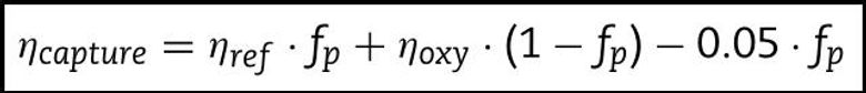
We can quantify our discussion of energy efficiencies by formulating an expression for the overall plant efficiency:
Equation 4: Abanades et al., 2007
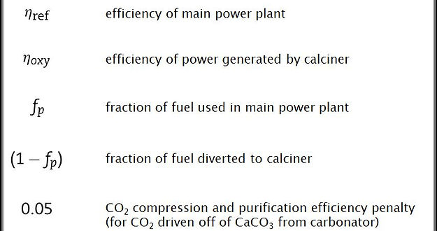
The various terms in the above equation have the following meanings:
Abanades et al., 2007
The overall power plant efficiency is just the sum of the efficiencies of each process, weighted by the fraction of the overall power that is generated by that process. It is assumed that the fraction of power produced by each process is equivalent to the fraction of fuel consumed (in this case, coal), so the overall plant efficiency is the sum of the efficiencies of each process weighted by the fraction of fuel used in that process. The first product in the equation describes the efficiency of the reference power plant, which is just the efficiency the whole plant would have if it were composed only of the main power plant without employing any form of carbon capture technology. The second product contains the information related to efficiency of the calciner, which basically operates independently as a mini oxy-fired coal power plant. The efficiency of the carbonator does not explicitly appear in the above equation because it is incorporated into both the reference plant efficiency and the oxy-fired calciner efficiency. Finally, the last product represents the 5% net energy efficiency penalty associated with CO2 compression. However, it is important to note that the CO2 compression penalty is only for CO2 from one specific source, and this requires a short explanation. There are actually three sources of CO2 in the power plant: 1. CO2 that is captured from the flue gas in the carbonator, reacting with CaO to make CaCO3, and then burnt out of the CaCO3 when it reaches the calciner, 2. CO2 released by the oxy-combustion of coal that occurs within the calciner to heat it, 3. CO2 that is burnt out of the fresh limestone which is added to the calciner to regenerate the CaO sorbent. The 5% deduction in the above expression is only for the compression of CO2 from the first source. The compression penalty for CO2 from the second and third sources is already included in the term for the efficiency of the oxy-fired calciner.
Finally, we can put in some values for the various terms of the expression to estimate the energy efficiency penalty associated with a given power plant scheme. There are three main sets of values we can use: a pessimistic set, a best estimate set, and an optimistic set. The best estimate set uses numbers that are considered to be the most reasonable, the pessimistic set uses numbers for a power plant that doesn't take advantage of various possible heat recovery options or does so very inefficiently, and the optimistic set uses numbers for a power plant that efficiently employs various heat recovery mechanisms. The values, taken from Table 1 of Abanades et al., 2007, are as follows:
Using these values in the power plant efficiency equation, we obtain the efficiencies for the overall power plant including the carbon capture process. The difference between the reference power plant efficiency (the efficiency that the power plant would have without any carbon capture scheme) and the capture scheme efficiency (the efficiency of the whole power plant when it is utilizing the above described carbon capture scheme) gives the energy efficiency penalty. Values for these three quantities, for each of the three estimated scenarios, are calculated as follows (and also appear in Table 1 of Abanades et al., 2007):
The estimates for calcium looping energy penalties calculated above are within the range of typical estimates found in the literature. Most literature agrees that calcium looping will impose an energy penalty of 6% - 8%. Also, most literature agrees that amine based carbon capture technologies impose an energy efficiency penalty in the range of 9.5% - 12.5%. This means that at least in terms of energy penalties, calcium looping compares favorably to amine based technologies, which are currently one of the most explored options for carbon capture from point sources. This is significant because if further studies show this to hold true, then at least from the standpoint of energy efficiency, calcium looping is a viable alternative process for carbon capture that could be employed to combat global climate change.
References:
[2] Borgwardt RH. Calcium oxide sintering in atmospheres containing water and carbon dioxide. Industrial & Engineering Chemistry Research 1989;28(4)
[3] Bordwardt RH . Sintering of nascent Calcium Oxide . 1988
[4] Chen Z, Song HS, Portillo M, Lim CJ, Grace JR, Anthony EJ. Long-term calcination/ carbonation cycling and thermal pretreatment for CO2 capture by limestone and dolomite. Energy and Fuels 2009;23:1437–44.
[5] Fennell PS, Pacciani R, Dennis JS, Davidson JF, Hayhurst AN. The effects of repeated cycles of calcination and carbonation on a variety of different limestones, as measured in a hot fluidized bed of sand. Energy & Fuels 2007;21(4):2072–81.
[6] Fennell PS, Davidson JF, Dennis JS, Hayhurst AN. Regeneration of sintered limestone sorbents for the sequestration of CO2 from combustion and other
systems. Journal of the Energy Institute 2007;80(2):116–9.
[7] Li Y-J, Zhao C-S, Duan L-B, Liang C, Li Q-Z, Zhou W, et al. Cyclic calcination carbonation looping of dolomite modified with acetic acid for CO2 capture. Fuel Processing Technology 2008;89(12):1461–9.
[10] Sun P, Grace JR, Lim CJ, Anthony EJ. Investigation of attempts to improve cyclic CO2 capture by sorbent hydration and modification. Industrial & Engineering Chemistry Research 2008;47(6):2024–32